How to install an analogue Ammeter on a K40 Laser Cutter

As an Amazon Associate Wargaming3D.com will earn from qualifying purchases.
I originally purchased my K40 laser cutter without knowing a lot about them, and fell into the trap of purchasing an “Upgraded” K40 laser cutter with a lot of bells and whistles that I didn’t need, but lacking ones that I probably did need. One of these was an analogue ammeter, so I can measure the amount of power going through my laser. But I have a digital % gauge on my laser you might say – which is all good and well, if we were dealing with a standardized machine, made by a single manufacturer – but because we are dealing with a cloned machine, we really have no clue what the percentage means – if you are running at 35% power … 35% of what exactly?
To put that in perspective, the conventional wisdom is that you shouldn’t run your laser more than 16mA (different articles will suggest 15-18mA max power, so increase at your own risk) with the 35W tubes that come with them (yes, they are mostly 35W, not the 40W as advertised for the 700mm long tubes, you get what you pay for), and if you are running a percentage gauge, you have no idea if you are putting 10mA or 100mA into it based on the percentage. This became a major issue for me, as I could never cut anything with the recommended percentages, which frustrated me, resulting in me replacing lenses, refocusing and all sorts of other things to try and achieve a cut into a 3mm piece of MDF in a single pass. It turns out, all I needed to do was to crank up the power a little more, and I was able to do so “safely” (you should always cut on the minimum power needed, and usually cutting issues can be fixed with proper alignment, focus and clean mirrors/lenses) … if only I’d actually known. For me, 16mA is around 53%, while for others in the K40 group its around 43% or event 35%!
With this in mind, I strongly suggest that one of the first upgrades you do with your K40 laser cutter is to install a analogue ammeter as soon as you feel comfortable doing so. With that being said, this does involve tinkering with electrical stuff in a K40, which is potentially lethal if you do it incorrectly. Everything you do from here on in is at your own risk, I accept no responsibility if you kill or injure yourself following these instructions, if you are unsure of yourself, get it done by someone who is qualified, each and every K40 is different so any guide is going to be unreliable and you need to also rely on your own electrical knowledge and common sense.
You will need:
I also found these useful:
- A Dremel tool or similar rotary cutter
- A crimping tool
- Insulated Electrical Screwdriver
- Hot Glue Gun
Here’s what worked for me based on following this guide at K40laser.se and the following video:
- Unplug the machine from the power and leave to sit.
- Work out how you are going to mount your ammeter on your case. Some people might want to do it on the removable panel which if you have the space, I strongly reccomend cutting a new one from acrylic and doing it that way, my upgraded one had no space because of the controls, so I needed to put it somewhere on the chassis, which meant cutting it.
- Use a Dremel Rotary tool to cut the hole for your gauge. You should put a plastic bag down to protect the electronics from metal shavings (I didn’t, and I’m sure I’ll blow it up eventually with something that most likely fell into the PSU – don’t be me). Test fit and remove any metal shavings from inside the case.
- Attach the guage to the K40 laser and clearly mark which end is the positive and which is the negative.
- Cut two lengths of wire to size from a roll of wire, one will be your positive and one will be your negative end of the wire. Attach a crimp terminal to one end of each.
- Find the negative wire from the laser and remove it from the PSU, you’ll want to cut it a few inches from the terminal that goes into the PSU.

The negative wire on my K40 is the black one on the far left. Double check by following the path back to the laser. - Connect the positive wire to the laser end of the negative wire and attach to the positive end of the ammeter.

Apologies for the Potato photo, but here are the wires connected to the ammeter. - Connect the negative wire to the negative end of the ammeter and attach to the negative terminal on the PSU.
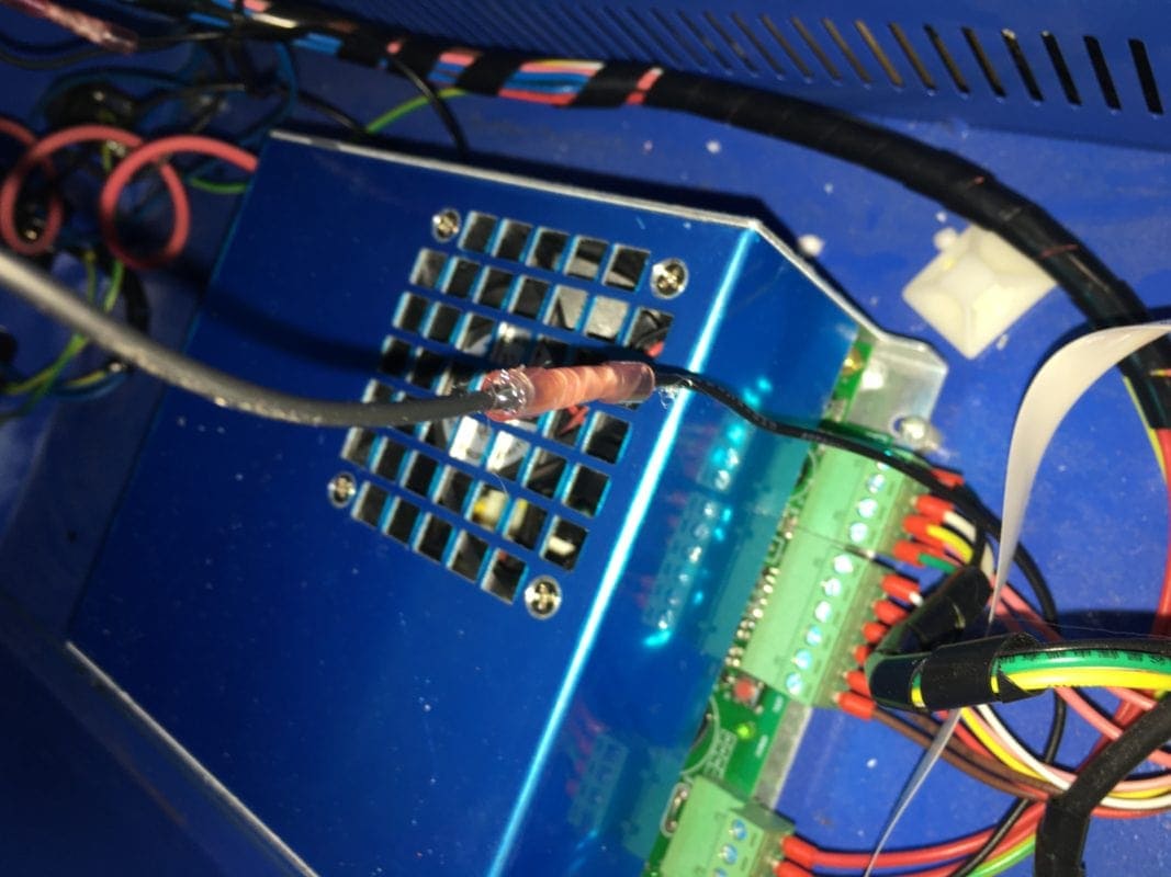
Wire from the PSU to the negative side of the Ammeter. Excuse my dodgy looking wiring, I don’t have a heat gun/soldering iron, so have crimped and hot glued the wires. . - Double check all connections are secure, and nothing is touching any bare metal
- Zero the gauge and test fire the laser, to ensure that everything is working.

Another potato quality photo, but here it is firing at 16mA (max power) at 53%. - Dab some hot glue on the bare metal connections, to ensure they don’t come loose, you don’t want this to happen and have a live wire connect to your chassis, this could kill you.